Lens field of view
Use the camera's actual horizontal view at the operating zoom.
 IR & Project Lighting
Optical Selection Guide
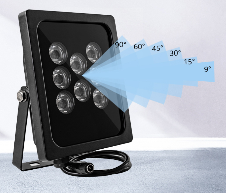
A narrower IR beam concentrates light into a smaller footprint and can support a more distant target, while a wider beam covers more of the camera scene. The correct angle is the one that overlaps the lens field of view at the target distance without a severe hotspot or dark edges.
Decision First
Use the camera's actual horizontal view at the operating zoom.
Measure from the illuminator and camera positions to the target zone.
Define the width that needs usable illumination, including edge tolerance.
Account for the angle between camera, light and target to reduce shadows and reflections.
Selection Snapshot
| Beam direction | Typical fit | Risk to check |
|---|---|---|
| Narrow | Distant, focused target or telephoto view | Alignment sensitivity and hotspot |
| Medium | Balanced distance and scene width | Edge coverage at target |
| Wide | Nearer or broad camera view | Reduced intensity at distance |
| Multiple beams | Segmented or complex scene | Overlap, power, aiming and maintenance |
For a simple symmetrical beam, an approximate footprint width can be estimated as: 2 × distance × tan(beam angle ÷ 2). This is a planning estimate, not a guarantee of uniform usable light.
Compare the estimated footprint with the camera's horizontal field of view at the same distance. Leave practical tolerance for aiming, lens changes and the softer edges of a real beam.
A distance value without a beam angle says little about coverage. A narrow unit may illuminate a small distant target while failing to cover a wide scene; a wide unit may cover the scene but deliver less intensity at the far edge.
Also check camera aperture, shutter, gain, sensor response, target reflectivity and weather. These determine whether the illuminated footprint produces a useful image.
Aim the illuminator while viewing the camera image. Check center, corners, near field and far edge, and look for reflections from plates, signs, walls, glass or foliage.
Record the final aim, mounting angle and camera settings. If a single beam cannot cover the required zone evenly, discuss multiple units or a revised camera/target layout.
Project Recommendation
Include the camera lens, target distance and width, mounting height and light position. We will help check the footprint before sampling.
Clear Answers
It concentrates light, but usable distance still depends on output, camera, lens, target, alignment and conditions. A beam that misses part of the view is not a successful choice.
Usually allow some aiming tolerance, but excessive extra width wastes light. Compare both footprints at the target distance and confirm with a night test.
The beam may be narrower than the lens view, misaligned or affected by mounting offset. Lens vignetting and scene reflectivity can also contribute.
Send target distance and width, camera lens or field of view, mounting height, camera and light positions, target movement and any reflective surfaces.

